SW+ Project Build - Stage 5 The Front End
Build instructions by Paul M0BMN
< Previous Next >Stage 5 The Front End
Ok So we are now going to finish off the RX side of our kit
So lets first sort out the parts we are going to use for this stage
Resistors
| R15 | 47K Ohm | Yellow-Violet-Orange |
| R16 | 22K Ohm | Red-Red-Orange |
| R17 | 2.2K Ohm | Red-Red-Red |
| R18 | 1M Ohm | Brown-Black-Green |
Then The capacitors
| C1 | 330pf | Ceramic Disk Marked '331J' or '331' |
| C2 | 47pf | Ceramic Disk Marked '47J' or '47' |
| C3 | 10pf | Ceramic Disk Marked '10J' or '10' |
| C4 | 2700pf | Small Yellow Pillow Type Marked '272J' or '272' |
| C5 | 2700pf | as above |
| C6 | 2700pf | as above |
| C7 | See Note Below | See note below |
| C8 | 68pf | Ceramic Disk Marked '68J' or '68' |
| C9 | 10pf | Ceramic Disk Marked '10J' or '10' |
| C10 | 270pf | Ceramic Disk Marked '271J' or '271' |
| C11 | 22pf | Ceramic Disk Marked '22J' or '22' |
| C101 | 0.1uF | Small Yellow Pillow Type Marked '104' |
| C103 | 0.01uF | Ceramic Disk Marked '103J' or '103' |
After that lets sort out the semiconductors
Only 3 parts
D1 This is a varcap diode not like the ordinary diodes and it looks different too (MV1662)
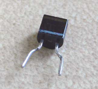 This is the Varcap diode (looks like a transistor with a leg missing!
Next we need Q2 which is a transistor Marked 2N4401
Finally we need another NE612/602 device and its socket
Now we need the inductors for this stage, one of which we make our selves ,
no don't panic , many people fear winding toroids, they are easy to do and we will look at that in more detail below
Inductors
RFC1 radio
freq choke locate din the little bag with some thin red wire and a yellow piece
of paper with 2 special diodes taped to it The choke we need is 10uH which is
coloured with bands like a resistor that needs to go on a diet! its bands are
Brown-Black-Black-Gold
T1 which is square shiny metal box with a screwdriver adjustable slug at one end and 5 pins at the other., this is a 10.7MHz IF transformer (we are not using as that though!
and finally the dreaded toroid, this is the VFO coil so its important to get this right but its not hard.
Read the instructions that came with the kit page 3, that tells you all you really need to know but here is some more help.
Find the small Yellow core (like a yellow polo mint!:-)
Its only yellow on one side! Now we need to consider what part of the band (80m) we want our radio to work, i want mine (i guess you will too) to work with a top freq of around 3.565MHz to get there we need to wind 20 turns of wire on this core, not 19 or 21 it needs to be 20 , is that clear.
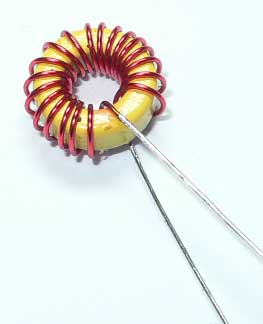
now look at the picture below and tell me how many turns is there on the core
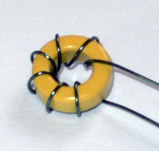
There are 7 turns on this core can you count them?
Ok lets get this VFO coil wound, read the instructions again that come with the kit (page 3) to make sure you understand how to 'Sow' this coil, its easy!
use the thicker red wire in bag that the RFC choke was in
follow the instructions and you will have a coil that looks like mine below
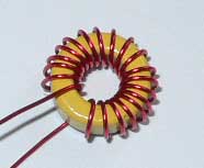
I think you can just about count the turns and see that we do have 20, space your turns like the ones in this picture after you have finished and trim the two leads to about 1 inch or so.
Ok Now we have all the parts lets start fitting them
Now lets fit the resistors starting with R15 to R18
The only point of note here is that R17 is shown the wrong way round on the silk screen, if you look at the instruction manual it shows this on Page 12 Group 4 drawing, you can also see it on the picture below.
Next fit the capacitors but not C7 we will come to that at the end of this section.
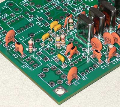
Here all the resistors and capacitor (except C7) are fitted , note R17 position.
Now onto the semiconductors and sockets
Fit D1 (MV1662)
make sure you align it with the outline on the board
Fit Q2 (2N4401) again make sure its aligned with its outline on the PCB
Now fit the 8 pin Socket for U1
Now move onto the inductors
Fit The RFC Choke
RFC1 (Note you will have a hole left above this choke with nothing in,don't
worry we come to that later)
Now fit that metal can Inductor T1 next, bend over the two metal lugs from the
can and solder them too.
Now the VFO Coil
needs fitting, first we need to strip the insulation from the leads, this can
be done a number of ways,
my favorite way is to use a solder blob on the end of my soldering iron to melt
the insulation off the wire and tin it at the same time, the results are nice
but it takes some practice im sorry to say
 here is my coil ready tined and waiting to be fitted
Other methods
will also work well, some melt the insulation off with a match, some scrape
it off with a knife, how you do it
is up to you, after all you are doing this to learn too.
When its done we need to fit it here is my tip for nice snug inductors, first push it into the board, push it right down and solder it in, Do not cut any wire yet. Now while the board is upside down hold one wire with a pair of pliers and re-melt the solder joint while at the same time GENTELY pulling the wire, repeat this with the other side, the inductor should now be nice and tight on the PCB and not wobble if you touch it
Check that you have a good connection on both sides of the coil by using you meter on the back of the board on the ohms range, the coil should read as a short circuit, once you are happy that you have a good connection here than trim the coils leads.
Well Done you have finished the RX side of the rig, that wasn't to bad was it?
Your board should look like mine now
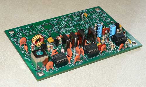
Now to work on the TX side in Stage 6
ONLY for
the Brave (or Stupid like me) Section
don't do this if you are new to building or have some degree of self control!
Ok Ok if you really want to you can connect up the board at this stage and get it working on Rx, im not going to offer any help with that, if you know what your doing its not hard just two pots and a few wires, I must admit to having done that with mine and im listening to it now as I type this, I needed to fit a 22pf cap for the range I want at C7 but if your not going to play with your radio yet we will come to that later so just move onto the next stage, out of interest the RX seems fine, plenty of signals that can be copied well, just a quick tune of T1 bought it to life my freq coverage is 3.525-3.566Mhz which is about 41Khz , for me that's just the part of the band I like, current drain was just under 16mA @ 11v (must recharge that SLA Now) I had it tuned on for a few min's while I was checking the freq coverage and current etc and when I tuned in a nice steady signal it seem to have no real drift from the vfo (a quick check showed about 20hz in 10 min's and it hasnt had chance to warm up yet!) ,Thats not bad at all for a LC VFO , my Elecraft K1 is not that good! when its finished I will measure it and report back.
< Previous Next > Back to SW+ Project Build page